Installation Planning
Mounting, power, basic connections
Place the chassis in a standard 19-inch rack. Follow your rack manufacturer’s mounting instructions for safe and stable mounting. If your 19” rack is not large enough, the Observer ships with a converter kit in the box. If your power supply has a 110/220 switch, make sure to set it to the proper voltage (120/220VAC, 50/60 Hz). Observer server power consumption specifications should be checked for the particular systems used.
Attach a dedicated keyboard, video, and mouse, so that during urgent service there is no delay in logging into the Observer. Alternatively, attach a KVM and a network cable to the rear of the machine to provide you with instant remote access. See the Observer Site Prep Guide for more details.
Power and Physical Rack Space for Servers
Plan for your rack space and cooling requirements by creating a table similar to the one below. List your servers and related site equipment. Include a one Client PC or laptop dedicated for use with the servers. We also recommend using a UPS, as unexpected shutdowns can cause harm to system operation.
Server/Equipment part number |
Description |
Power |
Rack Space High Multiples of 1U, (1.74 inch, 44.45 mm) |
2x 4-ANL-3U-090 |
Observer 2 Channel Analog |
2x760 W |
2x3U |
1U-WEB/SQL |
700 W |
1U |
|
1x Client PC |
400 W |
||
… |
|||
Total |
2620 W |
7U |
Power Circuit Distribution
Depending on which model of Volicon system you purchased, your Volicon server ships with dual power supplies. We recommend that you connect each power supply to a different/separate circuit. With this configuration, in the event that one circuit fails, the failing circuit will not cause total power loss to the system.
Total Power
Add the power requirements of all other onsite equipment to obtain the total power requirements.
Room Air conditioning
Ensure your wiring closed has sufficient cooling to handle the total power (Watts) of heat dissipated by the servers and your other onsite equipment as computed above.
Shelves for the STBs
If you purchased Observer STB or the Observer RPM S, we advise using Volicon shelf assembly’s 19 inch racks (482.6 mm) to store any Set Top Boxes delivering video and audio to the Observer server. The Shelves are only used with Observer RPM and Observer STB, and provide solid installation and good IR shielding. Locate the shelves close to the Observer server to reduce cable lengths. As an example see the STB shelf shown below. It fits in a 19 inch rack 2U high.
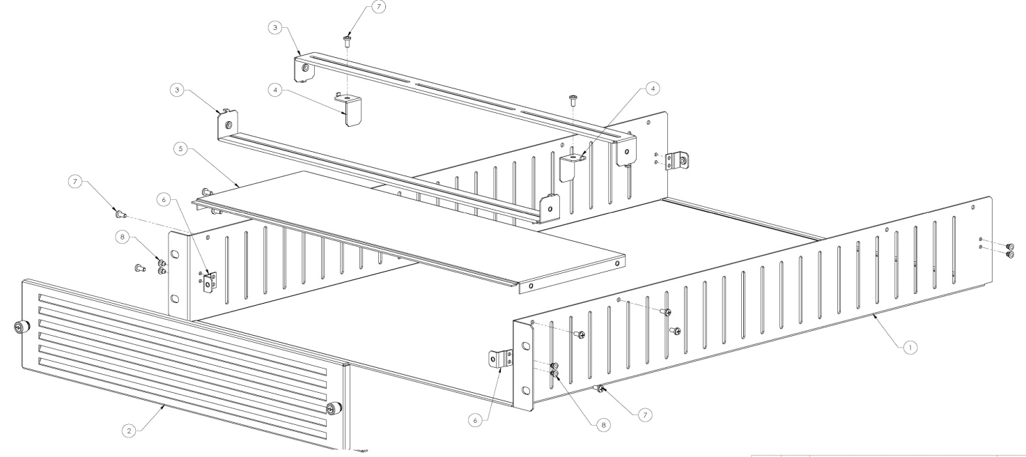
Figure: Set Top Box Mounting Shelf
Power ON, shutdown
After powering up the Observer server, wait for the login screen to appear. If you are logging into the system for the first time, consult Chapter 6: Initial Configuration or contact the Volicon support team.
After power-up, the Observer’s facilities run as services (configured by default) and do not require your input.
To shutdown, use the Start → Shutdown menu sequence. To restart use the Start → Restart menu sequence. Do not unplug the power cord so as not to impact the database. (Its re-indexing might require help from the Volicon support group). If for some reason the main Windows server console screen is not accessible, use the front panel button to perform the shutdown or restart.
We recommend connecting the Observer’s systems to a UPS or a similar high availability power supply.
Observer Front Panel Indicators
There are several LEDs on the control panel and others on the drive carriers to keep you informed of the overall status of the system and the activity and health of specific components. The chassis control panel includes a reset button and an on/off switch. This chapter explains the meanings of the LED indicators and the appropriate responses.
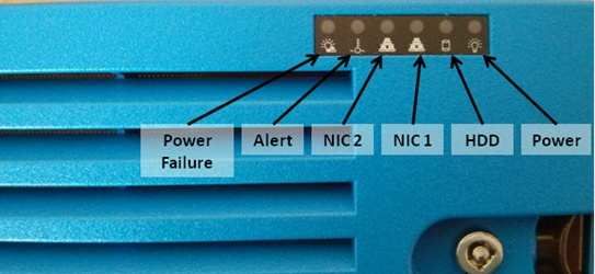
Figure: Observer Front Panel Indicators
Buttons:
Reset: The reset button is used to reboot the system, and is underneath the cover.
Power: The main power switch controls power from the power supply to the server system. Turning off system power with this button removes the main power but continues standby power to the system. Therefore, you must unplug the system before servicing it. The Power button is underneath the cover.
LEDs:
Power Failure: When this LED flashes, it indicates a power failure in the power supply.
Alert: This LED is illuminated when an alert condition occurs. See the table below for details.
Status
Description
Continuously on and red
An overheat condition has occurred. (This may be caused by cable congestion)
Blinking red (1Hz)
Fan failure, check for an inoperative fan.
Blinking red (0.25Hz)
Power failure, check for a non- operational power supply
Solid blue
Local UID has been activated. Use this function to locate the server in a rack mount environment.
Blinking blue
Remote UID is on. Use this function to identify the server from a remote location.
NIC2: Indicates network activity on LAN2 when flashing
NIC1: Indicates network activity on LAN1 when flashing
HDD: Indicates IDE channel activity. SAS/SATA drive and/or DVD-ROM drive activity when flashing.
Power: Indicates power is being supplied to the system’s power supply units. This LED should normally be illuminated when the system is operating.
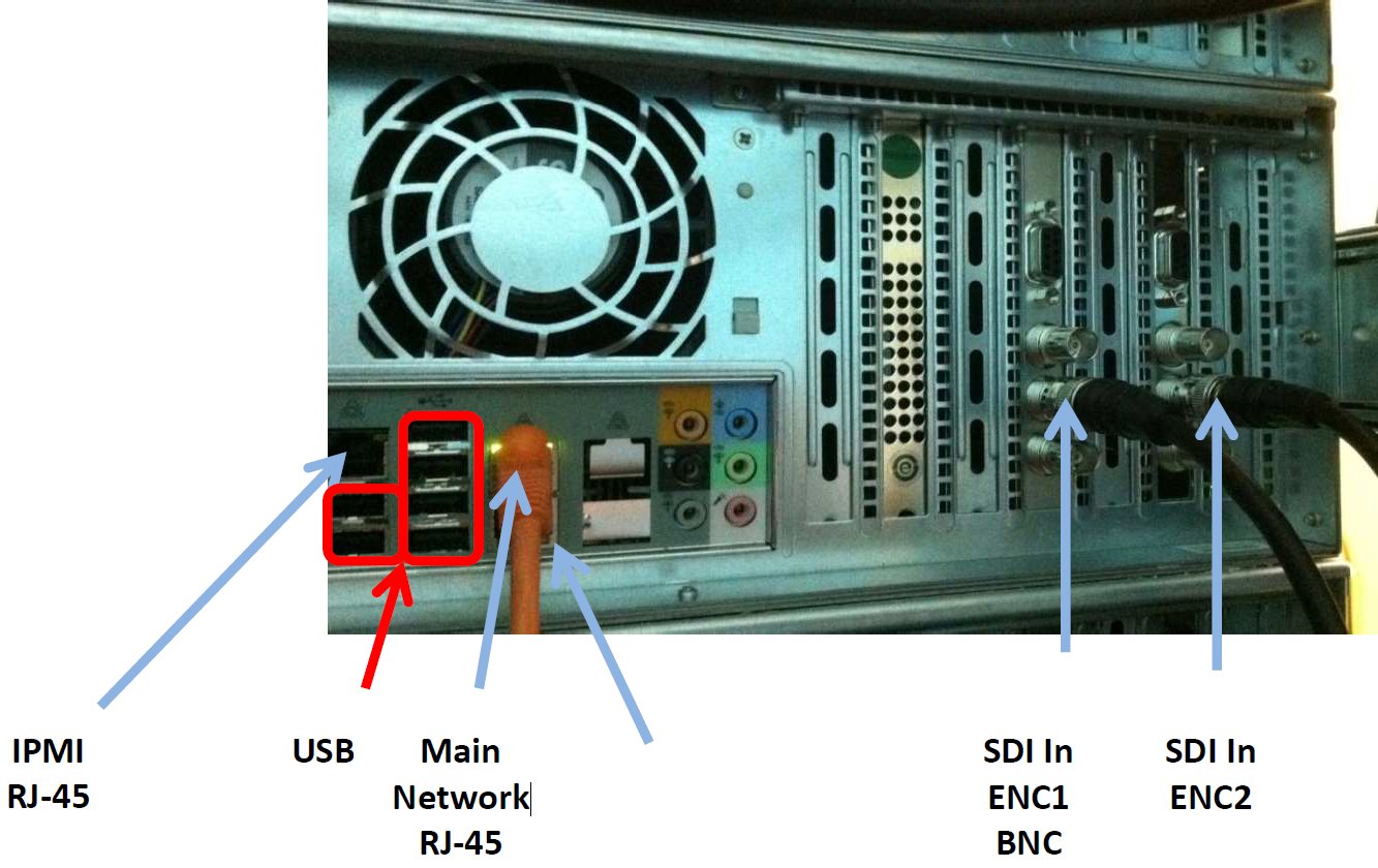
Observer Enterprise Chassis SDI Connections
The SDI-SD/HD connections on the Observer Enterprise Chassis are located on the back panel.