Pre-Installation STB Shelf Assembly Unit
Lay the Main Body of STB Shelf Assembly Unit on a hard and smooth surface. Identify the Front of the Main Body by the wings as indicated by Figure 4.1.
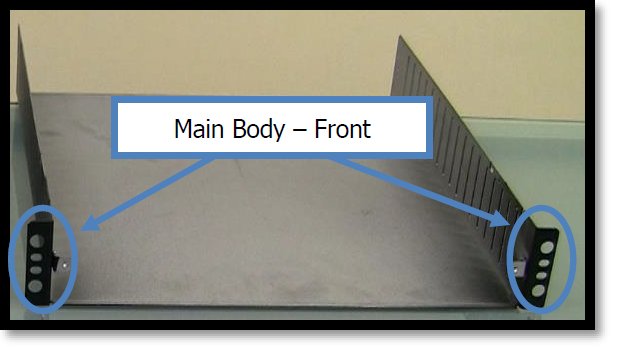
Figure 4.1. STB Shelf Assembly – Main Body Front.
Take (1) STB Securing Bracket with the securing tabs facing up and attach the UIRT Bracket to the middle slot using (2) Phillips Head Screws from the Mountaing Hardware. See Figure 4.2 for reference.
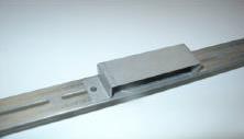
Figure 4.2. STB Shelf Assembly – UIRT Bracket.
Attach the STB Securing Bracket/UIRT Bracket Assembly to the Main Body
Mount the STB Securing Bracket/UIRT Bracket Assembly inside the Main Body. It is recommended to mount the STB Securing Bracket/UIRT Bracket Assembly at the third vent from the front and about a finger’s height from the bottom. These brackets however, may be mounted flexibly depending upon the dimensions of the cable box and desired proximity to the UIRT.
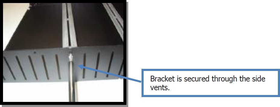
Figure 4.3. STB Shelf Assembly – Bracket Installation.
Take the remaing STB Securing Bracket with the securing tabs facing up and attach the (2) STB Stabilizing L-Brackets to the two outermoust slots using (1) Phillips Head Screws per L-Bracket. See Figure 4.4 for reference.
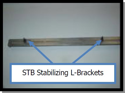
Figure 4.4. STB Shelf Assembly – STB Stabilizing L-Brackets.
Mount the STB Securing Bracket/STB Stabilizing L-Bracket Assembly inside the Main Body. This bracket should be mounted somewhere near the middle of the Main Body depending on the size of the STB being used. The Securing Screws should be kept loose at this time to allow for adjustment once the STB is installed.
Take the Comcast supplied STB and place front about 2 to 3 inches from the UIRT Bracket
Adjust the STB Securing Bracket/STB Stabilizing L-Bracket Assembly so that the Securing Bracket is touching the top of the STB and L-Brackets are snuggling grasping the sides of the STB. Once the desired fit has been achieved tighten the screws to the Assembly.
Take the USB UIRT and slide it in the USB UIRT Bracket with the sensor facing the STB.
Run the USB UIRT cable under the STB so that it comes out the back of the Main Body.
Next, take the Top Plate and secure to the Main Body. There are two screws on each side of the Top Plate that slip into notches in the front of the Main Body. Once in place, firmly press the Top Plate forward and it will lock into place. See Figure 4.5 for reference.
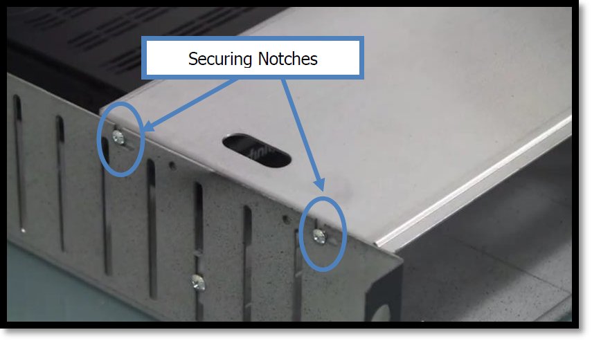
Figure 4.5. STB Shelf Assembly – Securing Notches.
Finally, place the vented 2U Shelf Front Cover into position at the front of the STB Shelf Assembly Unit between the Side Panel “Wings”. For reference see Figure 4.6.
Figure 4.6. STB Shelf Assembly – Shelf Front Cover.
Ensure that the Thumb-Screw holes on the (2) 2U Side Panels are aligned with the (2) Thumb-Screw holes on the 2U Shelf Front Cover. Once aligned, screw the (2) Spring Loaded Thumb-Screws into position.
Now that we have completed the assembly we will intall the STB Shelf Assembly Unit in the rack.
Take the two Short Brackets and secure to the front of the rack as shown in Figure 4.7. Allow for 2U above the Bracket.
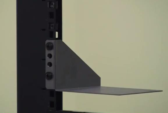
Figure 4.7. STB Shelf Assembly – Short Brackets.
Next, take the two Long Brackets and secure to the back of the rack at the same height as the Short Brackets. See Figure 4.8 for reference.
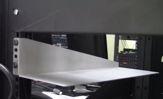
Figure 4.8. STB Shelf Assembly – Long Brackets.
Now that the Brackets are secure, take the STB Shelf Assembly Unit and from the front of the rack slide it in so that it sits on the 4 Brackets. See Figure 4.9 for reference.
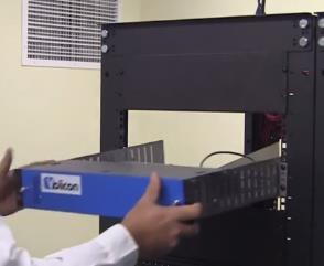
Figure 4.9. STB Shelf Assembly – Rack Installation.