Volicon Equipment Installation
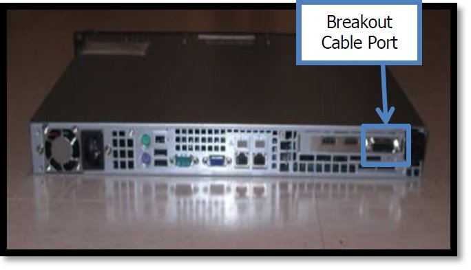
Figure 6.1 shows the Volicon Scout front and rear views.
On/Off Switch
Power Outlet
USB Ports
Ethernet Ports
HDMI Input Port
Breakout Cable Port
Figure 6.2 shows a close up of the Scout’s LED indicators:
Ethernet Connection light
HDD light
Power light
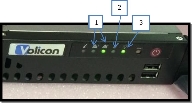
Figure 6.2. Front Right Face of the Scout - LED indicators.
The Volicon Scout Unit has been designed to slide into a standard rack withou the need for rails. Simply Slide the unit in directly above the STB Shelf Assembly Unit and secure the front Wings using the provided mounting hardware. See Figure 6.3 for reference.
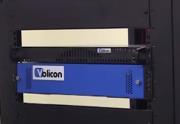
Figure 6.3. Scout Racking - Securing.
Install the power cable to probe and connect to the designated outlet.
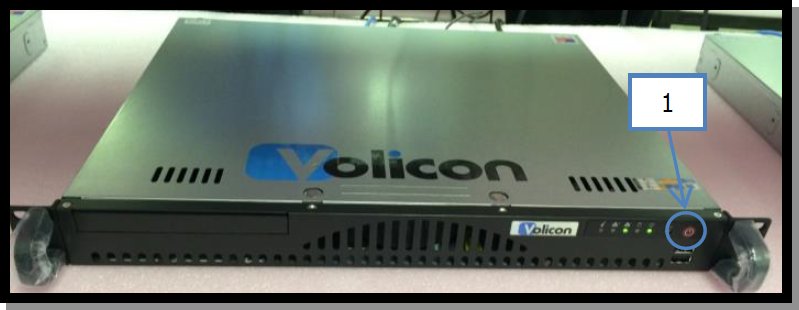
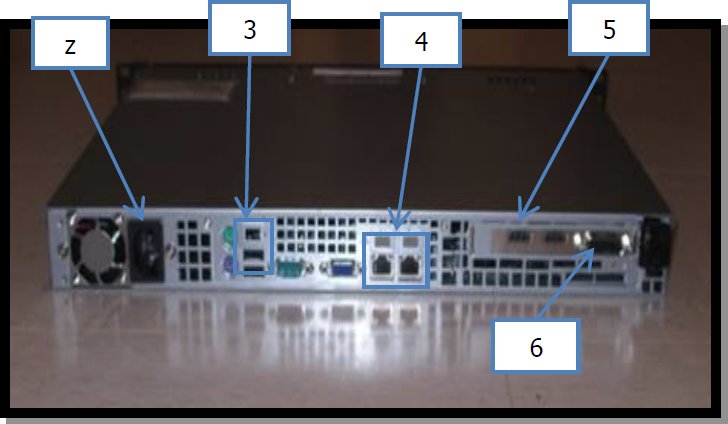
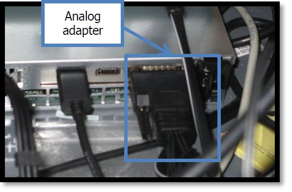
Figure 6.4 shows Volicon Scout rear view and location of the Composite port.
Connect the Analog Adapter to the outer most port located on back, right hand side of the Volicon Scout as shown on Figure 6.4.
Figure 6.5 shows the Long Male Component Adapter/Breakout cable. This is the same cable that was connected to the Breakout Cable Port.
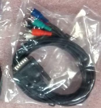
Figure 6.5. Analog Adapter (Breakout cable).
Connect the designated Network Drop (RJ45 Cable) to the right most Ethernet port (Eth 2) on the Volicon Scout when looking at the system from the back.
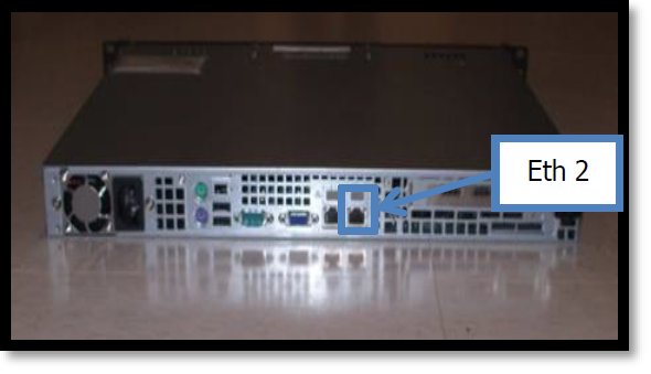
Figure 6.6. Volicon Scout – Eth 2
Power “On” the system by pressing the power button on the front right hand side of the Volicon Scout. Once powered up, the Power LED will turn on and the HDD LED will randomly blink as data is written or read from hard disk.
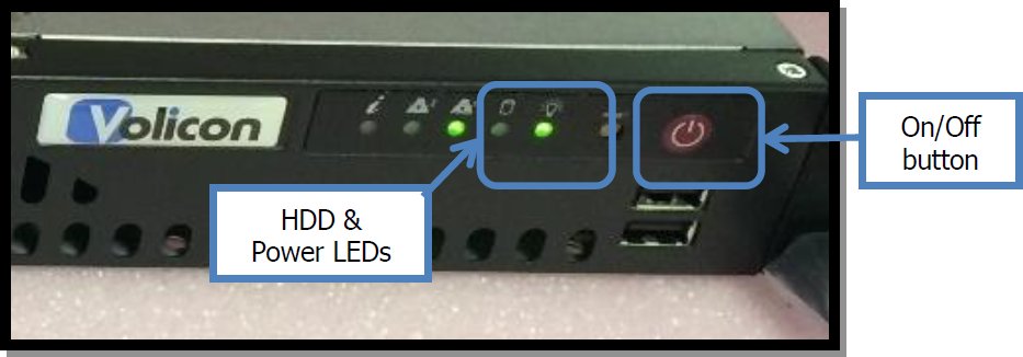
Figure 6.7. Right face of the probe - LED indicators and On/Off button.
Now that the Scout Unit is on, verify the Ethernet connection by confirming that the Eth 2 LED on the front of the Volicon Scout is now lit up. See Figure 6.8 for reference.
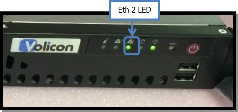
Figure 6.8. Right face of the Volicon Scout – Eth 2 LED indicator showing connection