Introduction
Purpose and Scope
This manual covers how to use the Volicon Observer’s Remote Program Monitor (RPM) for common monitoring and logging applications. It assumes that you administrator has set up alerting thresholds, and performed the user administration and general system configuration for your system as covered in the Observer Admin Guide. It also assumes that your administrator has completed the configuration functions related to the RPM, such as specifying the programs/services lineup to monitor, as covered in the RPM Admin Guide.
System Overview
The Observer system consists of two levels of servers:
One or more encoder servers (probes), usually located in remote or unmanned video distribution centers. Each encoder server is capable of monitoring several video inputs simultaneously, and is typically connected to four video sources through its encoders.
A Central/web server (CS) that functions as the interface between the system and the web client machines (client PCs).
Usually the system administrator configures the web and probe server addresses and functions of the system. These functions include:
Automated monitoring and diagnosis of multichannel broadcasts
VOD and Interactive service monitoring
Media recording of scanned channels
Manual viewing/diagnostics to tune remote systems
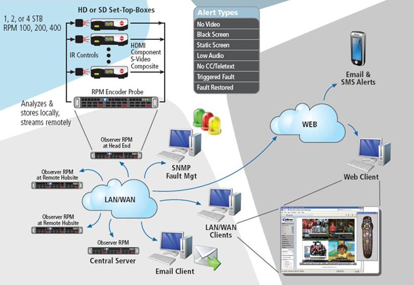
Figure: System Block Diagram
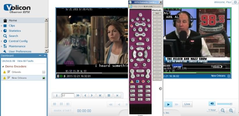
Once configured, the RPM constantly records video inputs and monitors channels for various failures. The RPM scans the channels your administrator has configured it to monitor, issuing channel change commands to each Set Top Box (STB), and monitoring all of the available channels on a rotating basis. When the RPM finds faults, it alerts you through email messages and SNMP traps.
You can access the RPM is via a standard Internet connection and control it through your web browser. RPM management is entirely web-based.
System Options: the Volicon Input Switch
By default, one input connects to one encoder in the Volicon ecosystem. However, the Volicon Input Switch allows you to connect multiple inputs to a single encoder.
You have two options for deploying the Volicon Input Switching capability: you can use the Observer’s internal switch, or you can connect multiple inputs to a KRAMER device.
Using the Observer’s Internal Input Switch
The Observer’s internal Input Switch capability will support up to two connections to a single capture card. Connect one component to the HDMI input, and the second component to the Component input.
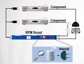
Figure: Internal Input Switch
Using a KRAMER device
You can connect up to sixteen components to a single capture card using a Kramer switch. In this deployment, the Kramer device handles the switching.
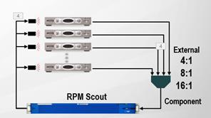
Figure: KRAMER Device Switching
The first input is the default input, and will be the only input you see in automatic mode. You can see the other inputs attached to your Volicon Input Switch only by using manual mode.
For more information about the Volicon Input Switch, please refer to the Volicon Input Switch User Guide V7.2.
Conventions Used in the Manual
Textual conventions used in this manual are listed in the table below.
Type |
Classification |
Boldface |
Denotes names and labels in the Graphical User Interface (GUI) |
<Boldface> |
Denotes push buttons and other similar user devices |
@Link |
Automatic link to other sections in the document, denoted by boldface and the “@” prefix |
Definition of Key Terms
Term |
Definition |
Encoder Encoder/stream |
Observer RPM hardware adapter that receives and processes media signals from between one to four set-top boxes. Also called the Encoder/stream. |
Encoder-scanner |
RPM software module which controls the encoder, STBs, and channel scanning related operations. See “Scan cycle,” below. |
Media Fault |
The services module defines the limits of normal conditions with thresholds, scripts and schedules for audio, video, closed captioning, interactive services and VOD. A Media Fault is detected when the input signal falls outside of these limits. |
Service, channel |
The Network’s media content type as perceived by the end user. The RPM steps through the lineup of services and converts each service (through bouquet) to a channel number, dialing it then recording and checking the content. |
Reviewer |
A separate encoder (or different time slot on the same encoder) assigned to verify a media fault on a channel. |
Alert |
A notification of a media fault by email or SNMP. For enhanced verification functions, confirmation is required from a second encoder or time slot before issuing the alert. |
Lineup |
A sequence of services associated with the channels of a encoder’s-stream. |
Scan Cycle |
A complete tour of all services/channels in a lineup to check for faults. 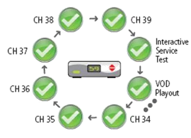
|
Modes of Operation
Here is a brief outline of the different RPM system modes of operation:
Scanning
RPM interacts with STBs to scan/dial multiple broadcaster channels sequentially according to the corresponding channel program type:
Linear
On-Demand
Interactive
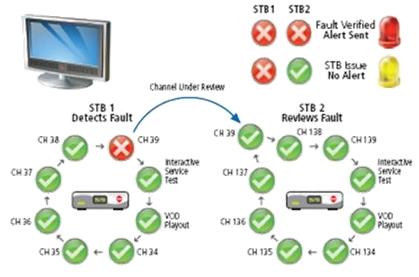
Figure: Scanning and Fault Response Process
In addition, the RPM monitors the media content of each scanned Service/channel to determine faults and log the content.
Reviewing
When the RPM detects a fault, it automatically reviews the fault using a second STB/Encoder stream. This allows the RPM to:
Dramatically reduce the number of false alerts
Separate STB faults from Network and Service Faults