Introduction
Product overview
Volicon’s Observer Remote Program Monitor (RPM) system is a powerful toolset for automated media monitoring and quality assurance in broadcast and cable networks, including features such as:
Automated monitoring and diagnosis of multichannel broadcasts
VOD and interactive service monitoring
Media recording of scanned channels
Manual viewing/diagnostics and remote system tuning
A Central Server (CS) web-based application is used for setup and user management, which means that a standard TCP/IP connection is all that is needed to have remote access to the RPM’s administrative features.
About this guide
The “Observer RPM Admin Guide” is intended for system and network administrators in charge of systems configuration and in need of additional information not found in the “Observer RPM User Manual”; the latter covers the common Observer RPM monitoring operations.
Please note that RPMs may be used with a standalone CS and one or more probe servers. If you need to install and configure the CS and Probe hardware, please refer to the “Observer Admin Guide” for details. For instructions on how to physically install the RPM probe in an equipment rack, please refer to the “Observer Site Prep Guide”.
This guide explains how to build the RPM database in configuring a list of services that the RPM will monitor; how to setup alert thresholds for the services and to configure scripts for the more complex service monitoring functions.
Definition of Key Terms
Element/term name |
Description |
Central server/ Web server |
In addition to web services, it provides centralized database, probe configuration and user administration. It is installed on a separate server unless there are very few probes in the system to manage. |
Probe server/ Encoder server |
Hardware chassis capable of accepting one, toup to eight encoder modules. Includes embedded software to manage chassis functions. |
Encoder/scanner |
Module installed in probe chassis, used to analyze video and media data. Dials/scans multiple channels to monitor them for media faults. May be purchased with optional software modules that enable other features. |
Media fault |
Detected when media content falls outside of the operational limits for audio, video and closed captioning |
Operational limits |
Parameters defined in scripts, e.g., thresholds and timeouts |
Broadcast service/ Service |
Content of network service perceived by the end user. Typically a cable or broadcast channel or a specialty/interactive service. |
RPM service/Service |
Automated function that refers to and interacts with a broadcast service. RPM service is also referred to as a service |
Lineup |
Administrator defined sequence of services for a scanner to monitor |
Scan cycle |
Monitoring all the services in a lineup to detect media faults and then getting ready to repeat the cycle through the complete lineup of services 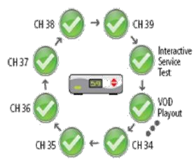
|
Reviewer |
An encoder used to validates the results of a scanner |
Alert |
Email and/or SNMP notification event in response to detecting media or system faults, if enabled to send an alert |
SNMP trap |
An alert sent to an external system through an SNMP protocol( used in general to manage devices on IP networks) |
System Overview
The Observer RPM system consists of a central server and one or more probe servers, these are often deployed in various strategic locations in the service provider’s operations, such as in the network management center, the operations center or in unmanned remote distribution hubs.
Probes are the building blocks of the system providing the physical housing for the encoder modules and related software. When broadcast and cable TV networks cover broad geographic areas requiring many encoder modules, the RPM system administrator often organizes the probes into related groups.
The CS interfaces the system to the web client machines (client PCs). Usually the administrator configures the web and probe server addresses and other parameters related to various functions of the system.
The following figure illustrates a simplified RPM deployment showing an example of the various components.
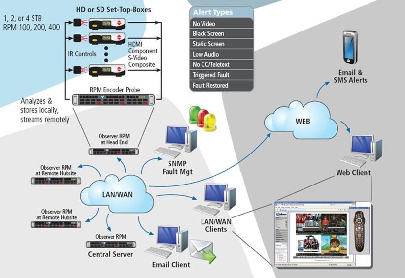
Figure: RPM system components in a typical network
Once configured, the RPM constantly records video inputs through its Probe/Encoder servers and monitors channels for various failures. It is done by scanning, issuing channel change commands to each Set Top Box (STB), thereby allowing the RPM to monitor all of the available channels on a rotating basis. When faults are found the system alerts the user through email messages and SNMP traps. Accessing the RPM is possible via a standard internet TCP/IP and is entirely web-based.
Observer RPM Interface to Broadcasting
The RPM systems interface with the broadcast network/streams through the encoder modules. The physical interface needs to be setup properly with the same parameters as the broadcast network to match it. The Observer can only monitor one broadcast program/service per stream. This section of the manual is referred to as “Stream level configuration”.
The RPM has additional functions to monitor various broadcast programs per stream by scanning the related services. This section of the manual is referred to as “Organizing services for scanning”.