Osprey
Volicon Media Intelligence service supports multiple Osprey capture cards. Osprey cards are used to ingest up to a maximum of four analog channels per card.
Osprey 260e
The 260e supports component, S-video and composite video and balanced or unbalanced stereo inputs.
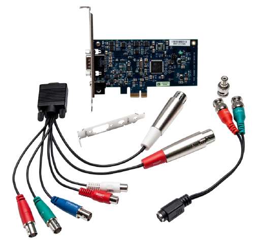
Figure: Osprey 260e capture card
Osprey 460e
The Osprey-460e supports four composite video inputs. It supports four BNC composite video inputs. A breakout cable is used to connect four stereo audio channels. The 460e replaces the earlier 450e.
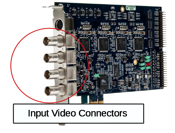
Figure: Osprey 460e capture card
The breakout connector provided with the Osprey card has four left/right, unbalanced audio inputs.
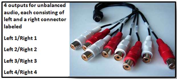
Figure: Osprey breakout cable
Volicon Media Intelligence service encoder channels are configured as follows:
Video Input A and Audio Left 1 / Right 1
Video Input B and Audio Left 2 / Right 2
Video Input C and Audio Left 3 / Right 3
Video Input D and Audio Left 4 / Right 4
Audio breakout cable 9 Pin Mini Din
The pin assignment for the Osprey 450e and 460e audio breakout is as follows:
1. Audio input |
Left 1 |
2. Audio input |
Right 1 |
3. Audio input |
Left 2 |
4. Audio input |
Right 2 |
5. Audio input |
Left 3 |
6. Audio input |
Right 3 |
7. Audio input |
Left 4 |
8. Audio input |
Right 4 |
9. Ground |
Ground |
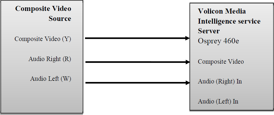
Composite video interconnect diagram
460e rack mount breakout panels
The 460e capture card supports rack-mounted breakout panels. These can be used to facilitate cabling or support balanced audio using industry standard XLR connectors.
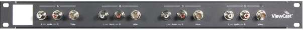
Figure: Composite video and stereo audio
It provides rack connection to the four composite video and stereo audio components. This is identical to the flying lead breakout cable.
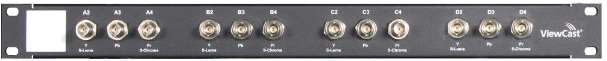
Figure: Video breakout panel
It provides rack connection to the four video channels configured individually as: component, S-video and composite.

Figure: Balanced audio breakout panel
Provides rack connection to four balanced stereo channels.