Server Front Panel Indicators and Controls
For security purposes a locking front cover prevents access to drive bays, auxiliary drives, and the power and reset buttons. With the security panel installed, only the system level status LEDs are visible.
Note: there may be minor differences in Panel Indicators depending on the specific server and configuration.
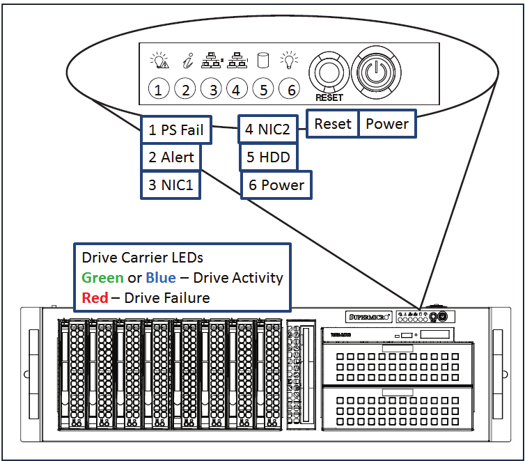
Figure: Typical Server Indicators and Controls (Security Panel Removed)
Power On and Shutdown
To power up the server remove the locking front panel security cover and press the Power switch.
After powering up the MIP server, wait for the login screen to appear. If you are logging into the system for the first time, consult the “Read Me First” guide or contact the Volicon, a division of Verizon Digital Media Services support team.
Note: MIP runs as a service (configured by default) and does not require a user/admin log in to operate.
To shut down MIP, from the console use the MS Windows <Start>→<Shutdown> sequence. To restart the server, use the <Start>→<Restart> menu.
Caution
DO NOT remove power or press the Reset button to reboot the server. This uncontrolled shutdown can corrupt the application database, and require re-indexing by a MIP support engineer).
If the Windows UI is not accessible, use the front panel <Power> button to perform an orderly server shutdown.
Server Front Panel Indicators
There are several LED indicators on the control panel and others on the drive carriers, to keep you informed of overall system status and the activity and health of specific components. This section explains the meanings of the LED indicators and the appropriate responses.
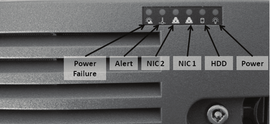
Figure: MIP Front Panel Indicators (Security Panel in Place)
Indicators:
 Power Failure: When this LED flashes, it indicates one of the power supplies has failed.
 Alert: This LED is illuminated when an alert condition occurs. See the table below for details.
Table: Chassis Indicators¶ Alert Status
Description
Constant red
An overheat condition has occurred. (This may be caused by cable congestion.)
Blinking red (1Hz)
Fan failure, check for an inoperative fan.
Blinking red (0.25Hz)
Power failure, check for a non-operational power supply.
Constant blue
Local UID has been activated. Use this function to locate the server in a rack mount environment.
Blinking blue
Remote UID is on. Use this function to identify the server from a remote location.
 NIC2: Indicates network activity on LAN2 when flashing.
- NIC1: Indicates network activity on LAN1 when flashing.
 HDD: Indicates IDE channel activity. SAS/SATA drive and/or DVD-ROM drive activity when flashing
 Power: Indicates power is being supplied to the system’s power supply units. This LED should normally be illuminated when the system is operating.
Drive Carrier Indicators
Each drive carrier has two status LEDs. They are normally hidden behind the security panel. Remove the panel to access the drive bays.
Green or Blue: Drive activity. Flashes when drive is accessed.
Red: Drive Failure.