General Interconnect Description
Media SD Video/ Audio and HDMI Interconnections
The Set Top Boxes (STBs) for Audio/video outputs at positions P2, P3, P4 and P5 interconnect with the 3 RU RPM Encoder Server in position P6. See “Figure: STB Rear Panel” shown below:
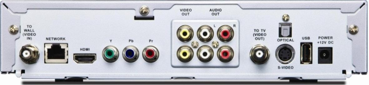
Figure: STB Rear Panel
The STBs at P2 P3 P4 and P5 interconnect with The Observer Encoder Server Blackmagic Intensity Pro Video cards at positions C1 C2 C3 and C4, see “Figure: Chassis Rear Panel” shown below:
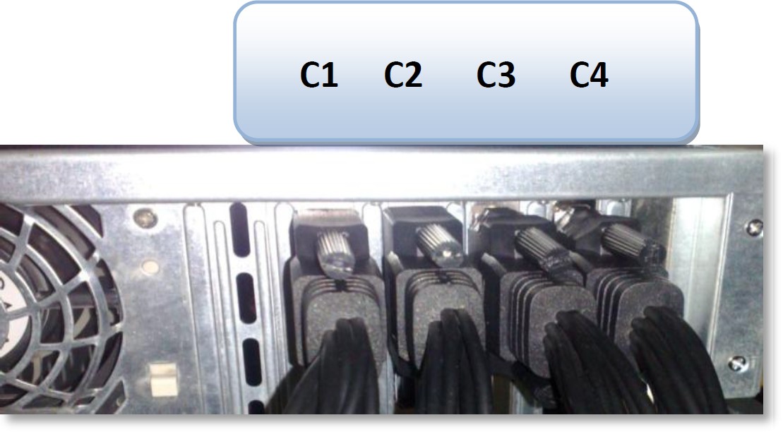
Figure: Chassis Rear Panel
The STB interconnections with the media capture cards are as follows:
STB Location |
Card position |
Type of Connection |
Type of Cable |
P2 |
C1 |
Composite video S-Video |
Use Intensity Pro breakout cable |
P3 |
C2 |
Composite video S-Video |
Use Intensity Pro breakout cable |
P4 |
C3 |
HDMI and Component Video |
HDMI and Intensity Pro breakout cable |
P5 |
C4 |
HDMI and Component Video |
HDMI cable for HDMI and Intensity Pro |
IR Transmitter Interconnections
When an Observer is used to change STB channels, it uses IR transmitters for it. Each IR transmitter connects to a four port USB hub which is connected to the RPM Encoder server. The following IR transmitters should be mounted at the following shelf positions:
IR Transmitter USB- UIRT device |
From |
To STB Shelf position |
USB-UIRT |
USB hub |
P2 |
USB-UIRT2 |
USB hub |
P3 |
USB-UIRT3 |
USB hub |
P4 |
USB-UIRT4 |
USB hub |
P5 |