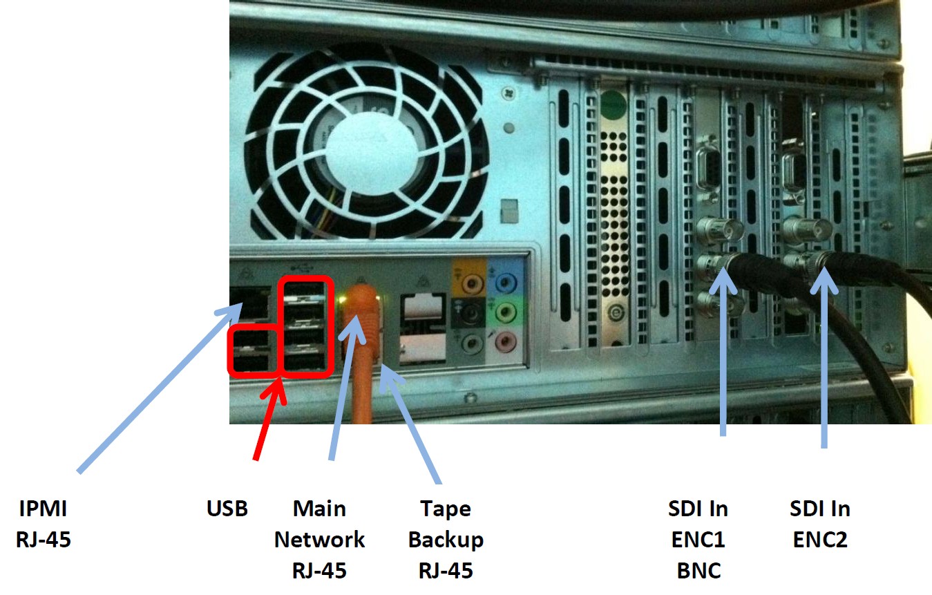
SDI-SD/HD System Interconnect
SDI-SD/HD Interface diagram
SDI-SD/HD interfaces use the following BNC cable interconnections
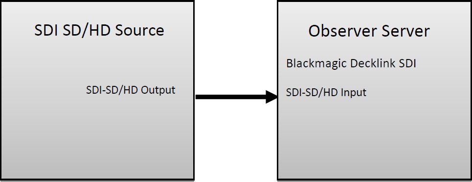
Figure: SDI-SD and SDI-HD Interconnect Diagram
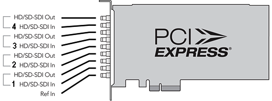
Blackmagic Decklink SDI
Observer supports the Blackmagic Decklink SDI.
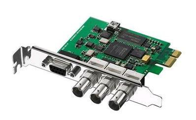
Figure: Blackmagic Decklink SDI Card
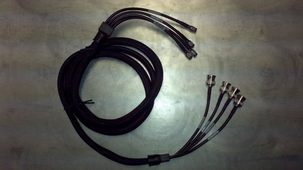
Decklink SDI Coax Connector Diagram
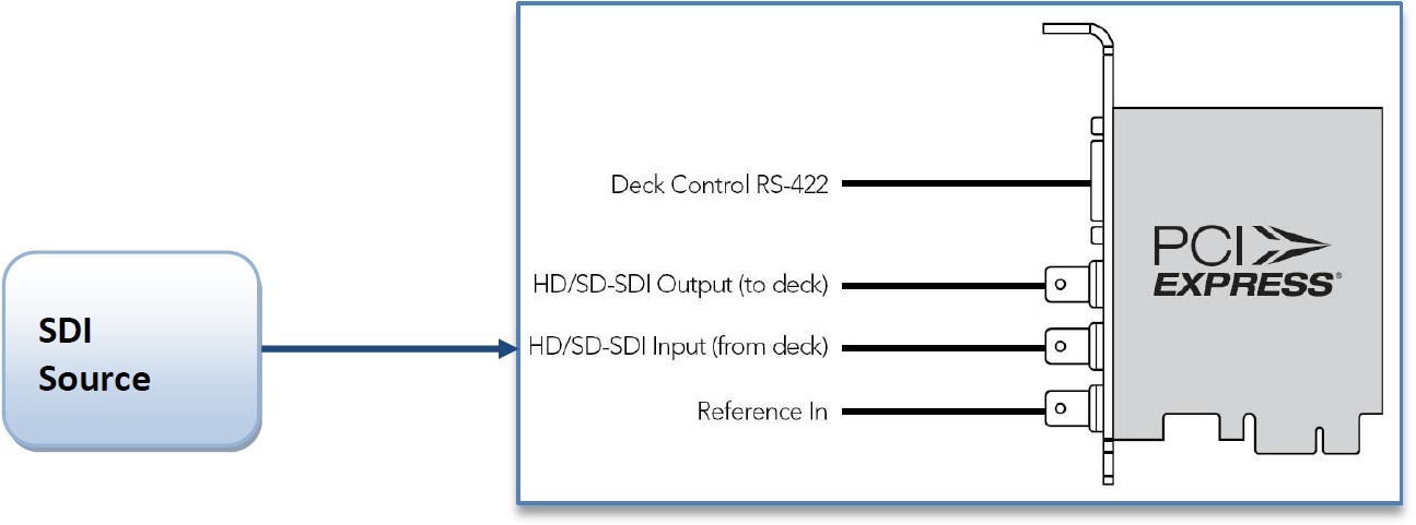
Figure: Decklink SDI Coax Connector Diagram
Connect the SDI Source (from deck) with coax M to the Blackmagic Decklink SDI card’s BNC connector Input.
Dolby Digital 5.1 Support
Dolby digital is supported in release 5.5 and above. Select the AC3 audio profile to setup Dolby digital on the Blackmagic SD encoder card.
Decklink SDI Channel features
For SDI-SD and SDI-HD applications with compatibility to NTSC and PAL, this card can be used either as a standalone or in large facilities with SDI routers. The A10 bit SDI video card features a tri-sync reference input, 8 channels of SDI embedded audio, 2 channels AES/EBU digital output with sample rate converters and RS-422 deck control. For the generic shelf interconnect see “Typical Rack Layout and Interconnect with STBs” at section @2.1.5.
Blackmagic Decklink Quad SDI–SD/HD
The Observer also supports the Blackmagic Decklink Quad SDI-SD/HD card. The card has Mini BNC SDI connectors, see the diagram below for connection details.
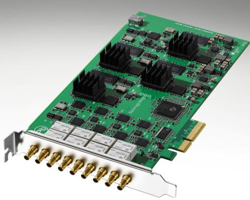
Figure: Blackmagic Decklink Quad SDI-SD/HD
Decklink Duo SDI/HD adapter interface
The DeckLink Duo Blackmagic adapter card supports dual HD/SD capability with two SDI interface connections to the adapter card through BNC connectors as shown below:
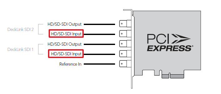
Figure: Decklink Duo SDI/HD adapter
Transport stream DeckTec interface
This card is configured and monitored by the Media Hubsnap in on the server desktop. See the TS Admin guide for more details about the configuration and monitoring of TS streams.
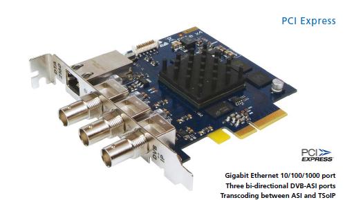
Dektec DTA-2160
The Dektec DTA-2160 has following connector ports for Gig E and ASI interfaces:
Physical location from top |
Port type |
Logical port number |
1 |
Gig E |
Port 4 |
2 |
ASI 1 |
Port 1 |
3 |
ASI 2 |
Port 2 |
4 |
ASI 3 |
Port 3 |
Note the location of the connectors for the interface links. The top connector is the Gig E connector, called port 4, followed by the ASI port 1; ASI port 2 and ASI port 3 interfaces.
Gig E Port 4 |
|
|
ASI 1 Port 1 |
||
ASI 2 Port 2 |
||
ASI 3 Port 3 |
||
